


Studieren an unserer Universität

Ein Studium an der Universität Luxemburg ist eine eizigartig bereichernde Erfahrung. Die Studiengänge vermitteln hochaktuelles Wissen in einem äußerst internationalen, mehrsprachigen und interdisziplinären Umfeld. Kleine Klassen sorgen für eine direkte Interaktion zwischen Studierenden und Lehrkräften.
Anträge auf Zulassung zu den Studiengängen für das Studienjahr 2025-2026 können ab dem 1. Februar 2025 eingereicht werden. Der Zulassungsantrag für das akademische Jahr 2025/2026 ist jetzt für Nicht-EU-Bewerber geschlossen. EU-Bewerber können sich noch für ausgewählte Studiengänge bewerben.
Finden Sie Ihren Studiengang
- Bachelor- und Masterstudiengänge Werfen Sie einen Blick auf unser Angebot an Studiengängen
- Doktorandenschule Erfahren Sie mehr über unsere Doktorandenausbildungen
- Spezialisierte Diplomstudiengänge Unsere Ausbildungsangebote für angehende Fachärzte
- Fort- und Weiterbildung Informieren Sie sich über berufliche Fortbildung und Möglichkeiten des lebenslangen Lernens
Aktualitäten
-
-
Junge Mathematikerin revolutioniert Wahrscheinlichkeitstheorie
Auszeichnungen & RankingsMathematikLearn more -
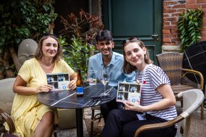
Alumni-Sommerfest: Eine unvergessliche Nacht – bei Regen oder Sonnenschein!
Campusleben, UniversitätLearn more -
-

Neuer CERATIZIT-Lehrstuhl bringt Innovation in Werkstoffen und Fertigung an die Universität
PressemitteilungenIngenieurwissenschaften, Physik & MaterialwissenschaftenLearn more -

Neues Universitätszertifikat in Luxemburg – „Autismus verstehen für eine bessere Inklusion
StudiumLearn more